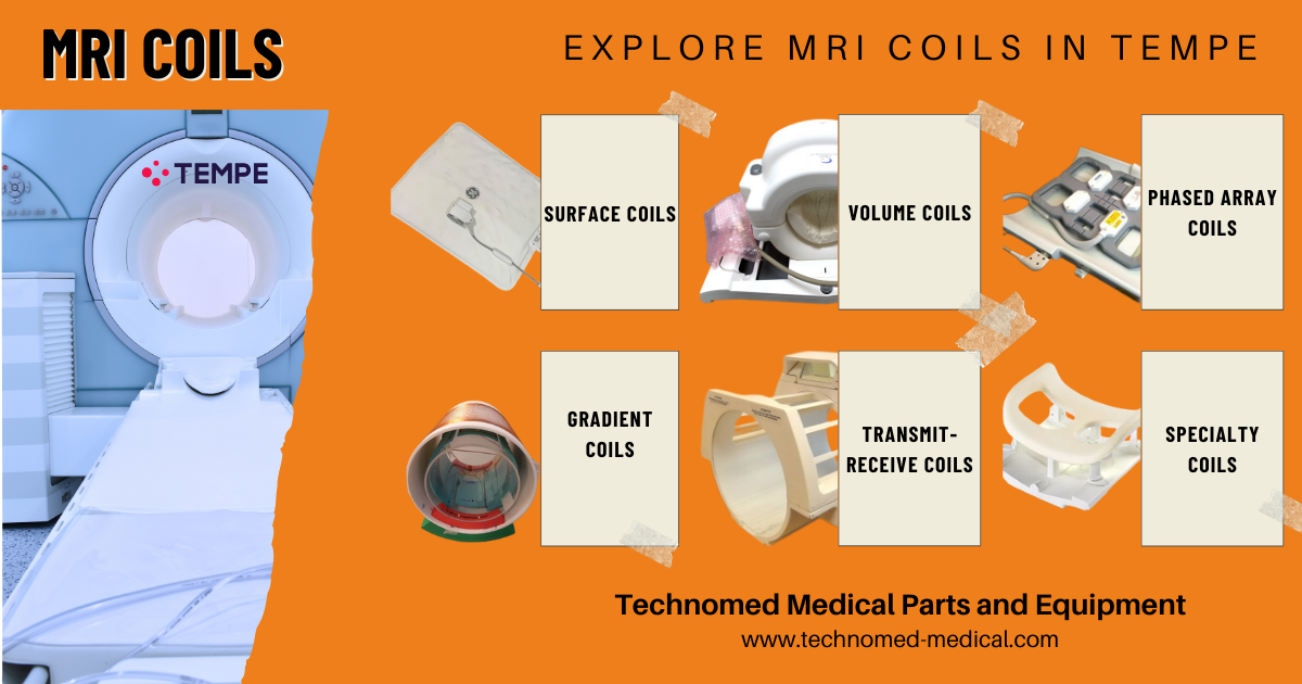
Magnetic Resonance Imaging (MRI) is one of the most important diagnostic imaging technologies used in modern medicine. At the center of every MRI system are MRI coils, which help transmit and receive radiofrequency (RF) signals during the imaging process.
Understanding the different types of MRI coils, their functions, and their applications is important for radiologists, MRI technologists, biomedical engineers, service companies, and healthcare facilities that manage MRI systems and replacement parts.
In this guide, we explain the main types of MRI coils, including surface coils, volume coils, phased array coils, transmit receive coils, head coils, body coils, breast coils, extremity coils, and specialty coils. We also explain how MRI coils are selected, maintained, and used in clinical imaging.
Technomed Medical Parts and Equipment supplies tested MRI coils and MRI replacement parts for GE, Siemens, Philips, Canon, and other major medical imaging systems.
| MRI coil type | Main use | Common applications |
|---|---|---|
| Surface coil | High resolution imaging of a small anatomical area | Knee, wrist, shoulder, small parts |
| Volume coil | Uniform signal coverage over a larger area | Head, body, pelvis |
| Phased array coil | Improved signal quality and larger coverage | Spine, abdomen, joints |
| Transmit receive coil | Transmits and receives RF signals | High precision imaging and research applications |
| Head coil | Brain and head imaging | Neuro MRI |
| Body coil | Large body region imaging | Chest, abdomen, pelvis |
| Breast coil | Dedicated breast imaging | Breast MRI |
| Extremity coil | Imaging of arms, legs, hands, and feet | Orthopedic and MSK MRI |
Introduction to MRI Coils
MRI coils are specialized devices designed to transmit radiofrequency signals, receive signals from the patient, or perform both functions depending on the coil design. In simple terms, they work like antennas inside the MRI system and play a direct role in image quality, signal strength, field of view, and diagnostic accuracy.
The quality of MRI images depends heavily on the type, position, compatibility, and condition of the coil being used. Different MRI coil types are designed for specific anatomical regions, imaging applications, and MRI field strengths such as 1.5T and 3T.
Types of MRI Coils
Surface Coils in MRI
Surface coils are commonly used MRI coils placed close to the anatomical area being scanned. They are designed to provide strong signal reception from a localized region and are often used when high resolution imaging is required.
Surface coils in MRI are commonly used for smaller anatomical areas such as the wrist, knee, shoulder, temporomandibular joint, and other small parts.
Advantages of Surface Coils
- High spatial resolution
- Strong signal to noise ratio in a localized area
- Suitable for detailed imaging of smaller body parts
Limitations of Surface Coils
- Limited field of view
- Requires accurate positioning
- Less suitable for larger anatomical areas
Volume Coils
Volume coils are larger MRI coils designed to cover a larger anatomical region. They can provide more uniform signal coverage and are commonly used for imaging the head, chest, pelvis, and other larger body areas.
Some volume coils can be used for both transmission and reception of RF signals. A common example is the birdcage coil, which is often used in head imaging.
Benefits of Volume Coils
- Uniform signal coverage
- Suitable for larger anatomical regions
- Commonly used for head and body imaging
Phased Array Coils
Phased array MRI coils use multiple coil elements arranged together to improve signal quality and anatomical coverage. Each element receives signal from a specific area, and the system combines these signals to create a high quality image.
Phased array coils are widely used for spine, abdomen, pelvis, joint, and body imaging because they provide better signal to noise ratio and larger coverage compared with a single surface coil.
Benefits of Phased Array Coils
- Improved signal to noise ratio
- Larger coverage area
- Better image quality for many clinical applications
- Useful for parallel imaging techniques
Transmit Receive Coils
Transmit receive coils perform two functions. They transmit the RF pulse into the body and also receive the signal generated by the patient’s tissues. These coils are often used in specialized imaging applications, high field MRI, and research environments.
Advantages of Transmit Receive Coils
- High precision in RF transmission and reception
- Useful for specialized imaging protocols
- Common in research and advanced MRI applications
Specialty MRI Coils
Specialty MRI coils are designed for specific anatomical regions or clinical applications. These coils help improve patient positioning, image quality, and workflow efficiency for targeted examinations.
Head Coils
Head coils are used for brain, skull, and neurological imaging. They are designed to provide high quality signal coverage around the head and are commonly used in neuro MRI examinations.
Spine Coils
Spine coils are used for cervical, thoracic, and lumbar spine imaging. They are often integrated into the patient table or used as dedicated coil arrays.
Breast Coils
Breast coils are designed for dedicated breast MRI. They support patient positioning and help produce detailed images for screening, diagnosis, and follow up examinations.
Cardiac Coils
Cardiac coils are optimized for heart imaging and are used in cardiac MRI studies that require dynamic imaging, motion compensation, and strong signal quality.
Extremity Coils
Extremity coils are used for imaging hands, wrists, elbows, knees, ankles, feet, and other orthopedic or musculoskeletal areas.
Are Gradient Coils the Same as MRI RF Coils?
Gradient coils are not the same as MRI RF coils. RF coils are mainly involved in transmitting and receiving radiofrequency signals, while gradient coils are responsible for spatial encoding by changing the magnetic field in specific directions.
Both RF coils and gradient coils are essential to MRI image formation, but they perform different functions. RF coils help create and receive the imaging signal, while gradient coils help define the location of that signal within the body.
How to Choose the Right MRI Coil
The choice of the correct MRI coil depends on several technical and clinical factors. Choosing the right coil can improve image quality, reduce scanning time, and support more accurate diagnosis.

Anatomical Region
The coil should match the body part being scanned. For example, a head coil is used for brain imaging, while an extremity coil may be used for knee, wrist, or ankle imaging.
Signal to Noise Ratio
A higher signal to noise ratio can improve image quality. Coils placed closer to the target anatomy usually provide better signal for that region.
Field of View
The field of view depends on the size of the area being imaged. Small anatomy may require a surface or extremity coil, while larger regions may require a body or phased array coil.
Field Strength Compatibility
The coil must be compatible with the MRI system field strength, such as 1.5T or 3T. Using an incompatible coil can affect performance and may create safety or system issues.
System Compatibility
MRI coils must be compatible with the scanner manufacturer and model. GE, Siemens, Philips, Canon, and other OEM systems may use different coil connectors, software requirements, and system configurations.
Condition and Maintenance
The physical condition of the coil, cable, connector, housing, and internal electronics should be checked regularly. Damaged coils can create image artifacts, intermittent signal loss, or system errors.
Emerging Trends in MRI Coils
MRI coil technology continues to improve as manufacturers focus on image quality, patient comfort, workflow efficiency, and advanced imaging applications.
Lightweight Coils
Modern lightweight coils are designed to improve patient comfort and reduce positioning difficulty during MRI examinations.
Wireless Coils
Wireless MRI coil technologies are being developed to reduce cable clutter, improve patient handling, and support faster workflow.
AI Enhanced Coil Optimization
Artificial intelligence can help optimize image acquisition, coil selection, protocol setup, and image reconstruction in advanced MRI systems.
Custom and 3D Printed Coils
Custom coil designs and 3D printed coil structures may support specialized research, patient specific imaging, and advanced clinical applications.
Maintenance and Troubleshooting
Proper maintenance helps MRI coils retain good imaging performance and reduces the risk of artifacts, downtime, and repeated scans.
- Routine cleaning: Clean coils properly to support patient safety and reduce contamination risk.
- Routine testing: Test coils regularly to identify weak signal, intermittent errors, or image artifacts.
- Cable inspection: Check cables, connectors, and strain relief areas for physical damage.
- Repair or replacement: Address damaged connectors, cracked housings, faulty cables, or signal issues as soon as possible.
- Proper storage: Store coils in a controlled environment to prevent physical damage and unnecessary wear.
Practical Applications and Use Cases
MRI coils are used in many clinical and research applications. The right coil helps improve image quality and supports accurate diagnosis across different medical specialties.
- Neuroimaging: Head and spine coils are used for brain, cervical spine, thoracic spine, and lumbar spine imaging.
- Musculoskeletal imaging: Surface coils, extremity coils, and phased array coils are used for joints, soft tissue, and orthopedic imaging.
- Cardiovascular imaging: Cardiac coils are used for heart imaging and dynamic cardiac MRI studies.
- Oncology: Breast coils, body coils, and specialty coils are used for tumor detection, staging, and follow up imaging.
Looking for MRI Coils or MRI Replacement Parts?
Technomed Medical Parts and Equipment supplies tested and verified MRI coils and MRI replacement parts for hospitals, imaging centers, service companies, and medical equipment resellers. We can help source MRI coils for different systems, including GE, Siemens, Philips, Canon, and other major OEM platforms.
Available MRI coil types may include head coils, spine coils, body coils, knee coils, shoulder coils, breast coils, cardiac coils, and specialty coils depending on inventory.
For available used MRI machines and MRI replacement parts, visit our MRI Parts section or contact Technomed with the coil model and part number.
Contact our team with the manufacturer, model, part number, field strength, and required coil type, and we will check availability.
FAQ About MRI Coils
What are MRI coils used for?
MRI coils are used to transmit and receive radiofrequency signals during MRI imaging. They play an important role in image quality, signal strength, anatomical coverage, and diagnostic accuracy.
What are the main types of MRI coils?
The main types of MRI coils include surface coils, volume coils, phased array coils, transmit receive coils, head coils, body coils, breast coils, extremity coils, and other specialty coils.
What is a surface coil in MRI?
A surface coil is placed close to the body part being scanned. It is commonly used for high resolution imaging of smaller anatomical areas such as the wrist, knee, shoulder, and small parts.
What is the difference between a surface coil and a phased array coil?
A surface coil usually covers a smaller localized area, while a phased array coil uses multiple coil elements to improve signal quality and cover a larger anatomical region.
Are gradient coils the same as MRI RF coils?
No. Gradient coils help with spatial encoding, while RF coils transmit and receive radiofrequency signals. Both are important in MRI, but they perform different functions.
How do I choose the right MRI coil?
The right MRI coil depends on the body part being scanned, MRI system model, field strength, clinical application, required image quality, and compatibility with the scanner.
Does Technomed supply MRI coils?
Yes. Technomed Medical Parts and Equipment can help source tested MRI coils and MRI replacement parts for different OEM systems depending on current inventory and availability.
Conclusion
MRI coils are essential for producing high quality MRI images. Each coil type has a specific role, from surface coils for small anatomical areas to phased array coils for larger coverage and better signal quality. Choosing the right MRI coil depends on the body part, MRI system, field strength, clinical application, and required image quality.
Technomed Medical Parts and Equipment supports hospitals, imaging centers, service companies, and resellers with tested MRI coils, MRI replacement parts, and medical imaging equipment solutions. For availability, please contact our team with the manufacturer, model, part number, and coil type you need.